Tony Hugo's 315mm f5 Newtonian on a Split-Ring Equatorial Mounting.
ALLEGRO GRADIENT EDITOR A Program to use colourful themes with Allegro
SPACE FX Planetary Animation Frame generator
SPACE FX TUTORIAL A Brief tutorial covering basic parts of SPACE FX
ASTEROID (Windows) Asteroid Finder - Windows (98...XP)  version
ASTEROID (Linux) Asteroid Finder - Linux (Fedora) version
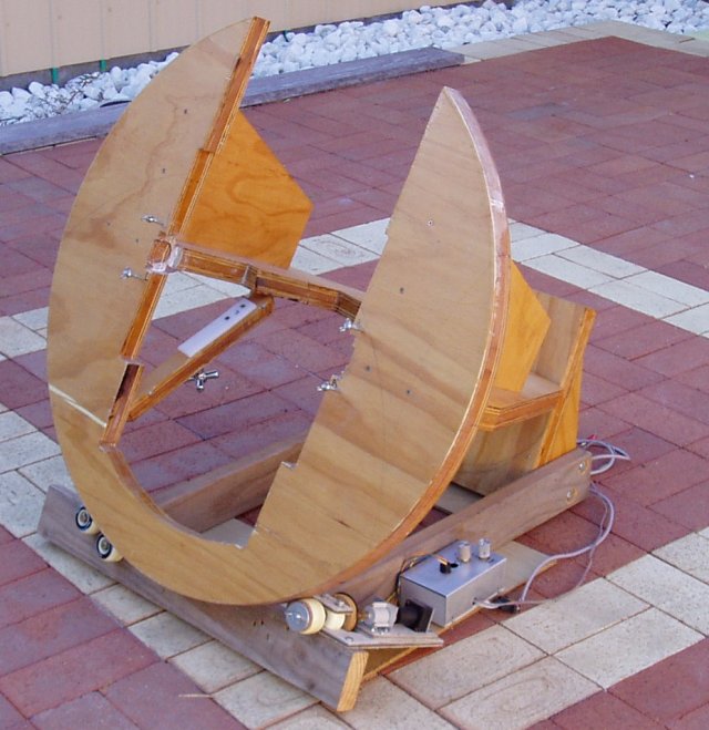
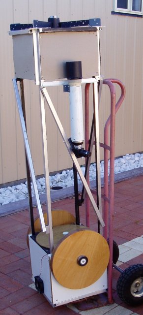
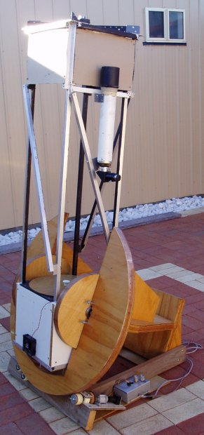
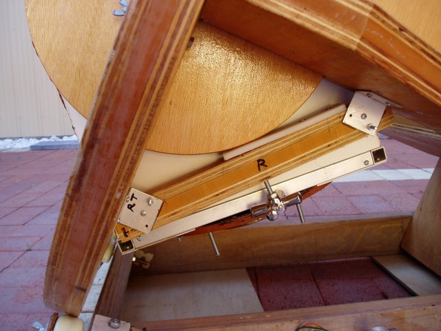
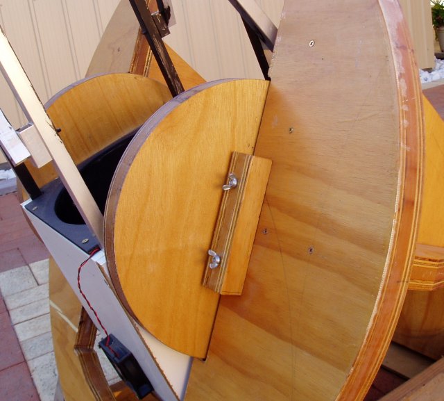
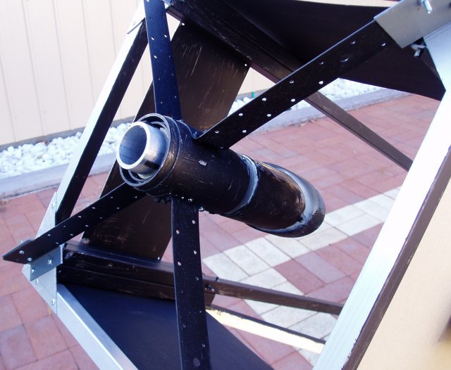
TELESCOPE and MOUNTING My 12.5 inch F5 Newtonian with a Split-Ring Mounting
TELEScoPIC - Digital Setting Circles Digital DSC using a PIC 16F628  microcontroller
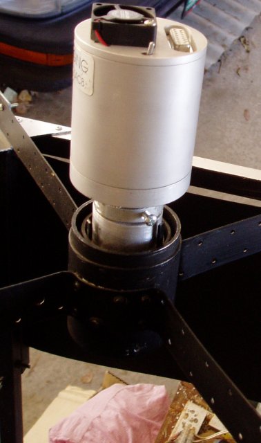
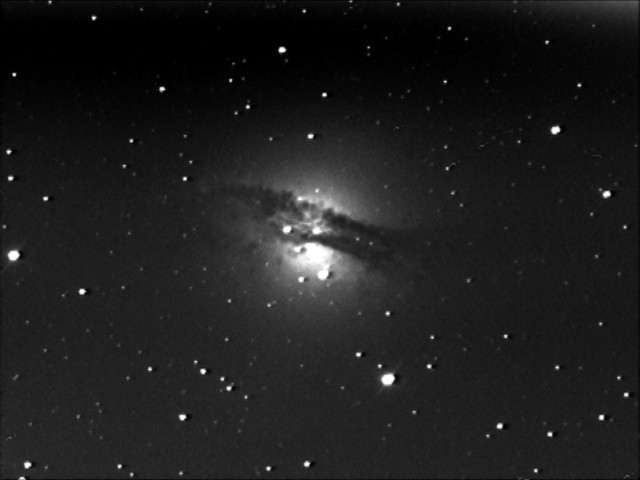
SAC8 CCD CAMERA My Pictures taken with a Telephoto lens and the SAC8-II CCD Camera
SAC8 CCD CAMERA -Page 2 My Pictures taken with the new Telescope Mounting
THE ORIGIN OF LIFE Musing on the Origin of Life, the Universe and Everything...


The Mounting started life as a sandwich of two sheets of 12mm plywood and one central core of 14mm MDF.
The three sheets were glued together with two part epoxy resin known locally as "Bote Cote" due to its use in the manufacture of small boats. As shown here, the two declination circles were cut out of the main ring. Not shown, is the backing piece for the base which was cut from the centre portion of the polar brace on the right. Before the cutouts were made, a router was used to shape the ring using a circle jig on the router. The edge of the ring was coated with fibreglass and epoxy before giving it a final cut with the router slightly larger than the first. Once the centre pivot is no longer needed, the centre piece can be cut out, along with the dec circles.
split ring components
The Dec circles can then be edged with a router, lined with fibreglass and carefully shaped so that they are identical. The centre point will be the place to attach the dec pivot bearings later.
The Polar brace can now be screwed to the Split ring at right angles and held square with an offcut on each side. The declination bearing is placed at the junction of the split ring and polar brace. To construct it, I assembled it together with the dec bearing clamps as shown below and carefully marked the centre, cut it using a hole saw and hollowed it out with a router set to the thickness of the roller bearings. Note that a small piece had to be chiselled out of the split ring bearing recess edge, so that the telescope can be placed (and removed) easily. The bearing was fitted using a bead of car body putty so that it fit snugly and can be clamped firmly.
bearing
After this it can be disassembled, coated with epoxy or varnish as desired then reassembled with screws.
The base (below) was thrown together using 90x35 timber with the north bearing housed in a small recess in the back plate.
A 30mm pipe is used as a polar axis. It protrudes out of the centre of the polar brace and fits into the bearing. I bored the hole in the polar brace with a 30mm spade bit to a depth of about 75mm and epoxied the pipe in place.
The base unit contains the drive system. The wheels (roller skates) are positioned to elevate the ring to the correct angle corresponding to your latitude, in my case, 25 degrees. I don't have any dimensions for this - I just trimmed everything untill it was right.
Having it this way meant that the ring assembly can be easily removed from the base. This makes transporting and set up very quick.

The drive system consists of a stepper motor salvaged from a floppy disk drive. It is connected to a Tamiya gearbox with a rubber cylinder salvaged from a photo print roller to reduce vibration. The gearbox (80:1 ratio) is coupled to the drive axis (an 8mm bolt)  with two brass gears from a mechanno set.  Chuck in odd bits of fibreglass, MDF, roller wheel bearings and you have a telescope drive!
Note that the drive wheel is free to rotate and is clamped to the shaft using a cork lined plate with a wingnut when the motor is used. It is shown below during preliminary setting up, before it was secured in place.

drive
Here are the two parts of the mount put together ready to accept the telescope.
Originally, the mount was designed for a 250mm telescope. However the mirror, purchased on ebay, turned out to be a shocker. So my family bought the 12.5" f5 mirror from Discovery Optics in the U.S.A. and I had to do a little butchery and creative design to make it all fit together.
base together
scope
The telescope is fabricated from 20mm aluminium tube. The mirror box panels are 16mm melemine shelving. The two dec circles are attached to the panels with internal screws and the dec bearings are held in place with coach screws in a 30mm wooden plug as a centre support.
A trolley makes transporting it easy.
mount+telescope
The telescope is lifted into the mount by hand. The weight is sufficient to hold it in place, but I have two small bearing clamps to secure it and provide a solid backing for the dec friction clamps below the polar brace. These clamps are made from a kitchen cutting board and a bolt that presses the board against the dec circles.
dec clamp
Here is a view of the dec clamps in place. The telescope mirror box has a fan (from an old computer power supply) to assist in cooling the mirror at night.
clamp
The secondary is made from alumunium tube supported by galvanised steel vanes. This secondary holder is designed for two functions. One, to support the secondary mirror in the usual fashion. Two, to support a SAC8-2 CCD camera for digital imaging when the secondary is removed. A single screw holds the secondary mirror assembly in place and it can be quickly removed for imaging sessions.
secondary
Since I use this "prime focus" position for CCD imaging, the secondary support is hollow and is accurately collimated to the optical axis using a laser collimator. This means that the CCD camera has a clear and unobstructed view of the primary. Since the camera is the same diameter as the secondary mirror, the cenral obstruction for the mirror is made no worse, and I avoid the light losses from the secondary mirror. It happens that the camera is about the same weight as the secondary mirror assembly. Therefore swapping the two makes for no adjustment in tube balancing.
sacsec
The only problem I have is that, with the "scraps and bits" approach to low budget telescope construction, I can only manage up to 4 second exposures before tracing errors appear in the CCD images. However the SAC8-2 CCD Camnera is a very sensitive unit!
Below is an example of what 9 x 4 second exposures can produce. This is NGC5128, the centaurus A galaxy.
ngc5128
SAC8 with telephoto lens
Asteroid Finder
Home Page

The Fine Print !
This HTML page and all contents, text, graphics etc, is the sole property of Anthony M. Hugo MIEAust CPeng, copyright 1999-2006. Permission is hereby granted to copy this material for personal use or educational use if the teacher isn't looking. Commercial use by corporate entities, colourful sporting identities and all you rich folks requires specific permission from me. So there!

Credits
Copyright symbols, logos and abbreviations are owned by copyright owners, logo designers and abr. ppl. Whatever happens, happens. But only sometimes!
I started life with nothing, and still have most of it left!
I always wondered whether anybody ever reads the fine print at the bottom of documents like this. My advise is to use an electron microscope. Cheers!